Thursday 7 January 2010

Cable Construction 1 core XLPE


Background of XLPE used

Early 1990's, began to be used for 11kV and 22kV.

The need to carry a load > 300A or 7 MVA

Example: interconnector between PMU-PMU, PMU-PPU or LPC (>10MW)

33kV 1C 630 mmp = 30 MVA
11kV 1C 500mmp = 10MVA
11kV 3C 240mmp = 6.7 MVA

Friday 1 January 2010

Current Transformer


A current transformer (CT) is a transformer which measures the current of another circuit. It is coupled to an ammeter (A in the diagram) in its own circuit to perform this measurement. Measuring high-voltage current directly would require insertion of measuring instrumentation into the measured circuit--an unnecessary difficulty which would draw down the very current meant to be measured. Also, the heat generated in the measuring equipment from the high current could give false readings. Measuring current indirectly with a CT is much more practical.

Application
Current Transformers (CT’s) are instrument transformers that are used to supply a reduced value of current to meters, protective relays, and other instruments. CT’s provide isolation from the high voltage primary, permit grounding of the secondary for safety, and step-down the magnitude of the measured current to a value that can be safely handled by the instruments.

Common Uses 

Electric Meter
The one central function of a CT is to determine the current in a circuit. This is especially useful for monitoring high-voltage lines throughout the power grid. Another ubiquitous use of CTs is in domestic electric meters. A CT is coupled with a meter to measure what electrical usage to charge the customer. 

Current Transformer
Another function of CTs is protection of sensitive measuring equipment. By increasing the number of (secondary) windings, N2, the current in the CT can be made much smaller than the current in the primary circuit being measured. In other words, as N2 in the formula i1/(2πr) = i2 --- N2 goes up, i2 goes down.

This is relevant because high current produces heat which can damage sensitive measuring equipment, such as the resistor in an ammeter. Reducing i2 protects the ammeter. It also prevents heat from throwing off the accuracy of the measurement.


Protective Relay 

CT Mounted Over Bushing of Circuit Recloser
CTs also protect the main lines of the power grid. An overcurrent relay is a type of protective relay (switch) that trips a circuit breaker if a high-voltage current exceeds a certain preset value. Overcurrent relays use a CT to measure the current, since the current of a high-voltage line could not be measured directly.

Thursday 31 December 2009

Magnetising Curve test


Test Terminal Block Female


Test Terminal Block Male

This tool is intended to test every relay in the control panel. Yesterday i went to PPU Tanjung Tokong  to see the contractor do the test for over current relay. Test whether the magnetic curve or not functioning properly.

Wednesday 30 December 2009

Current Transformer test


This person is one of the TNB's Contracter. They were doing testing for Current Transformer. They will inject current to secondary of the CT then the result to find the bending in curve.

Example: First result they get current value is 40 A then voltage they get 37 volt. for the next reading plus 50%  from previous read that means 60A the voltage result must get 10% from previous reading that means for 60A they must get 39.7V
Posted by Picasa

Monday 28 December 2009

Water Tree in XLPE Cable.


What is Water Tree?
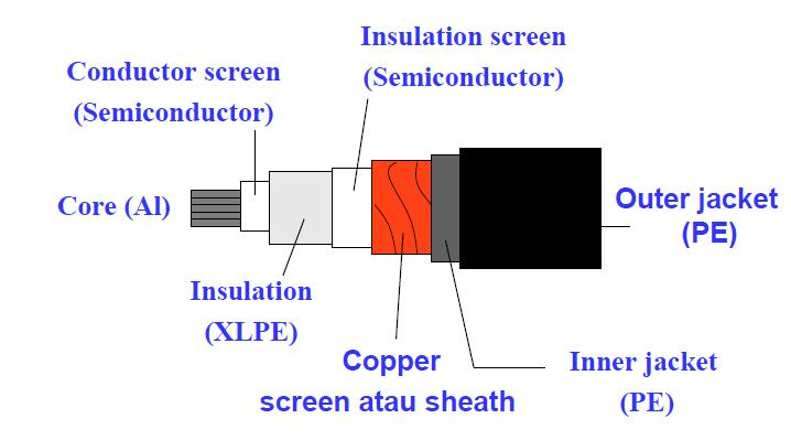
Water tree degradation is a major problem for medium voltage XLPE cables. One the Most important degradation process of the polymeric insulation that contributes to the failure of the cable

Why it call Water Tree? 
Water Trees are  a diffuse structure in the polymer resembling the shape of a tree or bush.

How it cause?
Water Tree are formed and grow in the presence of moisture, impurities or contamination@ and electric field over time.


There are generally two types of water trees, namely; )


Bow-Tie Tree


Vented Trees


Water Treeing - Bow-Tie tree

Bow-Tie trees are water trees that grows from the insulation outwards towards the surfaces of the insulation.
These trees grow in the direction of the electric field in both directions, towards the two electrodes.
Bow-Tie trees have faster initial growth rate as compared to vented trees.
Bow-Tie trees are however, not capable to growing to large sizes and usually do not grow to a size significant enough to cause failure of   the insulation

Water Treeing – Vented tree


Vented Tree are water trees that grows from the surface of the polymer inwards into the insulation  system.
 These trees will grow in the direction of the electric field.
 Vented trees have lower initial growth rate as   compared to bow-tie tree
 Vented trees are capable of growing right through the   entire insulation thickness.
 This is the more venomous of the two trees as these trees as it is of bridging the insulation system across two electrodes.

Sunday 27 December 2009

Finally finished load transformer

He he he. although yesterday a public holiday, but I still want to know how a transformer removed from the truck to the transformer plinth.


I think me already be late to witness loading transformer. But I am lucky. When I arrived  at PPU Kepala Batas they just start their work setup the accessories.


Thursday 24 December 2009

Transformer load

Today  I should can see how a transformer be shift to transformer plinth, but disappointing. The reason cause the lift that will remove the transformer not able reach in time because the transports punctured tyre in Gopeng, Perak. 

After that at 4pm I follow up position the lorry. they said already were in Bukit Merah, Perak. Inside possibility hit 6 in the evenings the truck will reach. 


From 2009-12-24 : 
workers are making preparations for the loading to Tx Plinth


From 2009-12-24
 Another transformer are waiting for loading

Before I forget the place at PPU Kepala Batas, Penang. Near to Pak Lah Badawi Hometown.
Below is about transformers' detail.


From 2009-12-24